How WebRTC Works
How do Peers Connect?
Let’s look at a high-level workflow of how a direct connection can be established between two peers. We will use an analogy of a peer Alice sending physical mail to another peer Bob.
How does Alice know where to address her mail to?

Alice will need some mechanism to exchange addresses with Bob to facilitate the delivery, which is known as signaling. This could be a text message or even a pigeon carrier. In practice, this is typically facilitated by a server.
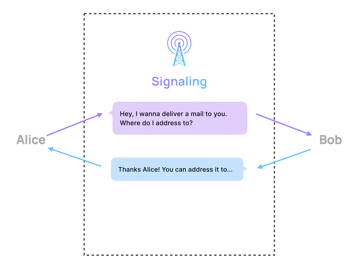
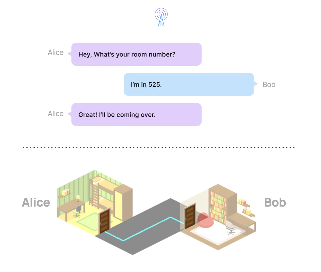
Let’s suppose Alice and Bob are in the same building. All communication passes via the signaling mechanism. Alice informs Bob that she is interested in sending him mail but she needs his room number. Bob responds with this information and Alice is then able to deliver the mail directly.
While this is ideal, what happens if Alice is actually in a different building than Bob?
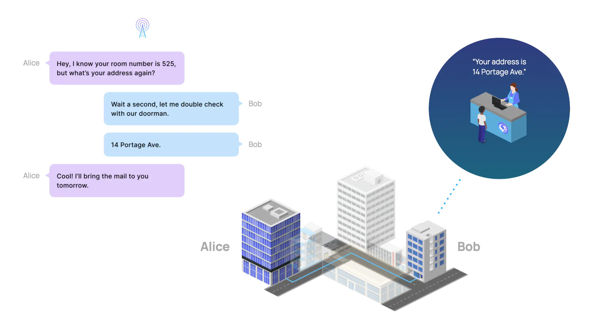
Alice and Bob may know each other’s room number, but this information is rather useless outside of their respective buildings unless they also know their buildings’ addresses. To find their respective building addresses, they can each ask their building doorman.
Now with a building address and room number, they can communicate this information using the same signaling mechanism. Alice can visit Bob’s building and deliver the mail herself directly.
What if Alice is traveling and ends up in a different city, state or country than Bob?
In this case, Alice is not able to directly deliver the mail to Bob herself, so she must resort to delegating the delivery work to a courier.
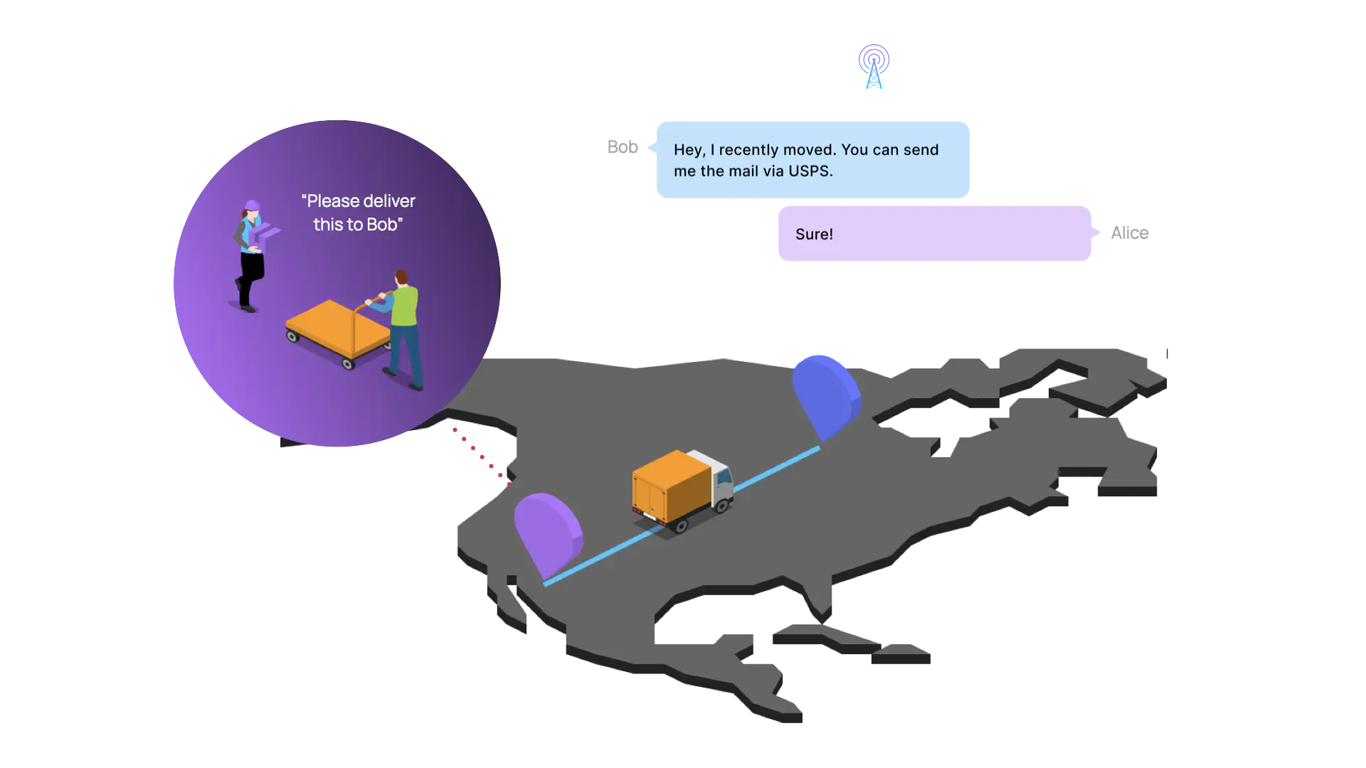
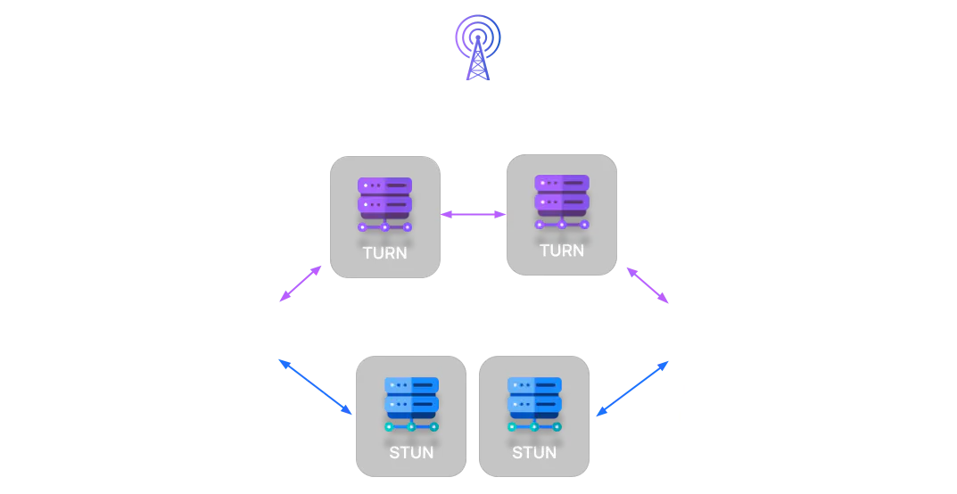
To summarize our analogy, for Alice and Bob to exchange addresses and connect there are up to three possible methods (delivering directly themselves or with the help of a doorman and courier). Each requires a different approach. Mapping this analogy to WebRTC, a signaling server and other servers (i.e. the building doorman and courier) are required in order to reliably establish a WebRTC connection (i.e. to deliver mail).
Next, we will take a more technical look at these components and discuss how they work together.
Technical Discussion
Signaling Server
The sole responsibility of a signaling server is to relay messages between peers who wish to connect. This relay allows peers to exchange critical information required to establish a direct P2P connection. However, the WebRTC specification does not actually describe how to implement a signaling server. Instead, the implementation details are left to the developer, since an existing backend infrastructure (serving some other purpose) could also be utilized to serve this function.
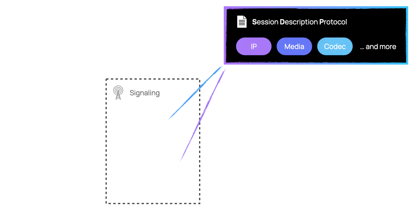
The structure of the information relayed is governed by the Session Description Protocol (SDP), a simple key-value text-based protocol. Some of the information contained within the SDP includes:
- The IP addresses through which each peer can be reached.
- The media streams, either audio, video, or both, that each peer wishes to send to the other peer.
- The different codecs available to both peers to encode and decode the media streams.
In WebRTC terminology, initializing a call requires peer A to send an “offer” to peer B who responds with an “answer”. The offer and answer represent each peer’s respective session description and these are exchanged through a process known as “negotiation”. With this information a direct P2P connection can be established.
This exchange of session descriptions occurs during the initial phase of the call but also any time the state of the session changes. If a peer decides to send a new media stream or begins experiencing network issues, a new “offer” and “answer” will be dispatched between the peers through the signaling channel. It is therefore not uncommon to have multiple negotiation phases between peers during a single session. The ability of the underlying application to handle this uncertainty regarding the state of the session is crucial in providing a seamless user experience. This is easier said than done, which we will explore when discussing the engineering challenges that we faced while building Otter.
Network Address Translation
One of the fundamental rules for all communication over the Internet is that every participating host must be assigned a public IP address. Under IPv4, an IP address represents a sequence of 32 bits divided into 4 octets of 8 bits each, which means that every octet has 2^8, or 256, possibilities. Therefore, there is an upper bound of ~4.3 billion on the total number of IPv4 addresses available in the world. With the ever-increasing number of devices connected to the Internet, engineers realized that this upper bound would be reached sooner than expected. To address this issue, Network Address Translation (NAT) was proposed.
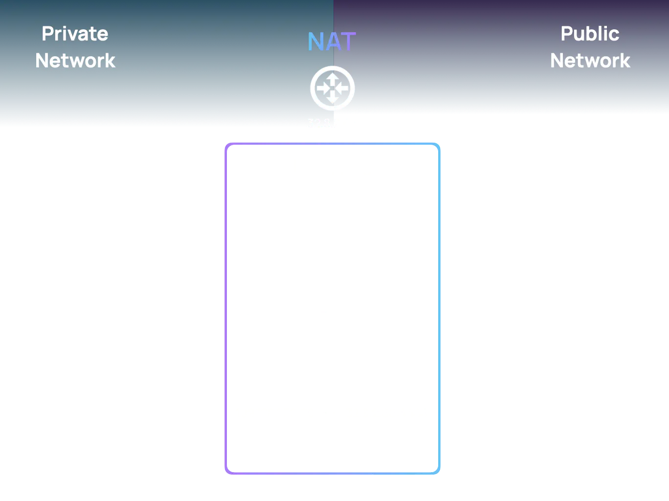
The NAT solution allows hosts within a private network to share a pool of public IP addresses to communicate over the Internet. For example, an internal host who wishes to send a message over the Internet will first send it to their NAT device, which will then change the source IP address on the packet to a public IP address chosen from its pool of available IP addresses. The NAT device keeps track of which hosts are currently assigned a public IP address to be able to route messages from the Internet to the appropriate internal host. Even though NAT does address some problems related to the availability of IP addresses, it also creates new ones for UDP traffic.
Recall every TCP connection has a well-defined communication flow. NAT devices rely on this underlying flow to determine when a connection is first established and when it is closed. This allows a NAT device to do the following:
- During the exchange to open a connection, assign a public IP address to an internal host for the lifetime of the connection.
- During the exchange of application data, route messages between the internal and external hosts.
- During the exchange to close the connection, remove the assigned public IP address and make it available to other internal hosts.
UDP, on the other hand, is connectionless. Unpredictable connection state is a major issue for NAT devices as they can no longer rely on the underlying communication flow to manage outbound and inbound packets appropriately. This makes it difficult for internal hosts to maintain a stable communication channel with external hosts. Since WebRTC relies on UDP, how does it resolve the missing connection state?
STUN & TURN Servers
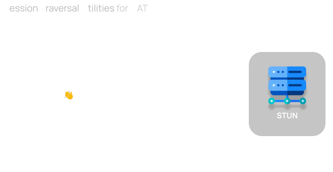
The answer lies within the fact that both peers need a public IP address. Like the room numbers inside the different buildings, a private IP address is useless outside of its private network. The solution is a Session Traversal Utilities for NAT (STUN) server.
A STUN server allows hosts within a private network to programmatically create a mapping in the routing table of the NAT device. The response of the STUN server will include a header indicating the IP address and port of the NAT mapping. STUN also periodically sends empty messages through the NAT device, which benefits UDP traffic by keeping the NAT mapping and thus connection state alive. This mapping can be relayed to the other peer through the signaling channel. Both peers now have a public IP address. Connecting…
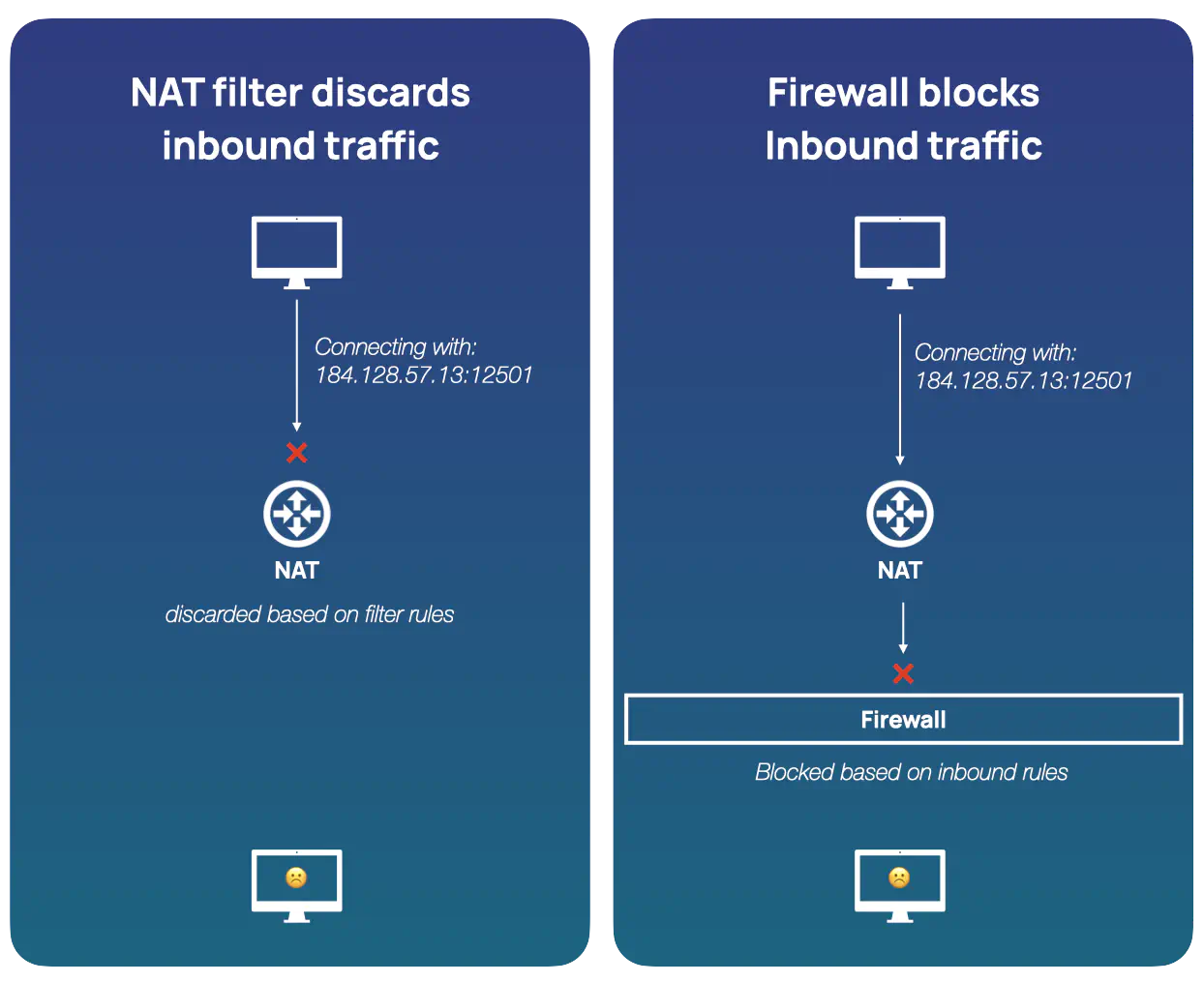
Not so fast! There are still situations where the above is not sufficient. When a NAT device creates a mapping within its routing table, it becomes responsible for routing outbound and inbound packets for the mapping. The way that inbound packets are routed and filtered can vary depending on the NAT device and its configuration.
In any case, inbound packets that are not allowed to use a specific mapping in the routing table are simply discarded by the NAT device. Depending on the filtering behavior of the NAT devices, communication between peers by using IP addresses and ports obtained through STUN servers may not be possible.
Furthermore, even if the NAT devices are not obstacles to a direct connection, private network firewalls can be. Firewalls can block traffic from certain port ranges or even block UDP traffic altogether. Analogous to how a courier helped Alice delegate her delivery, a workaround will be needed to establish a connection. The solution, a Traversal Using Relays around NAT (TURN) server.
If all else fails, a TURN server will act as a middleman between the peers. A peer that requires its packets to be relayed can simply send them to the TURN server. The TURN server then “dumbly” relays the packets to the other peer, without concern for its contents. The other peer is not aware that the packets are now being relayed.
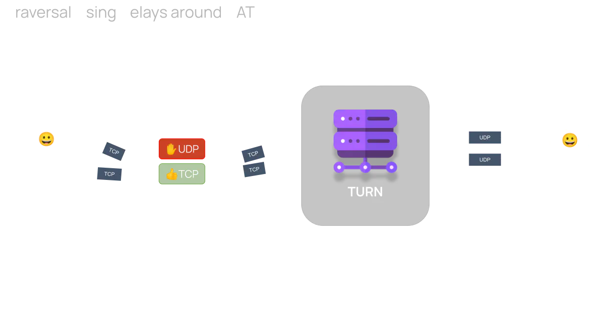
Using a TURN server is a last resort as it adds latency to the communication and increases the operating costs of the system due to the significant bandwidth usage. However, to allow a seamless user experience, it is a required component of the overall infrastructure. In reality, the aforementioned scenario requiring a TURN server only affects a small percentage of end users. According to documentation from a Google application1:
- 92% of the time the connection can take place directly (STUN).
- 8% of the time the connection requires a relay (TURN).
In summary, a successful connection requires both peers to gather multiple IP address and port pairs through which they could potentially be reached. In WebRTC terminology, a pair is known as a “candidate transport address”. These candidates are then exchanged between peers through the signaling channel. All possible combinations of candidates from both peers are then tested for connectivity establishment (i.e. if both peers have 3 candidates, 9 possible routes will be tested). Determining the most efficient path between peers on the network is critical and justifies the need for a STUN and TURN server in a WebRTC P2P topology.
